HK Series (Steel)
ISO 7241-1 B Interchange
Fluid transfer & Hydraulic application
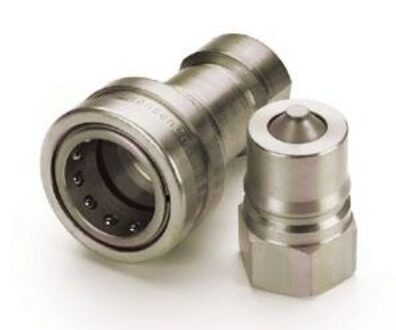
Danfoss Hansen HK Series coupling sets the industry
standard for ISO B Couplings. The HK Series features a
rugged ball latch mechanism with automatic self-sealing
poppet valves in a wide array of port configurations and
multiple valved and non-valved configurations.
Product Features
• Meets dimensional requirements to ISO standard
7241-1 Series B
• The coupling that sets the industry standard
• Self-sealing poppet valve design provides excellent high and low
pressure sealing
• Standard seal material: Nitrile (NBR)
• Seal options available in PTFE, Neoprene, FKM, EPDM, and Kalrez®
• Standard body material: Zinc trivalent plated steel with stainless
steel springs, balls and retaining rings.
• PTFE back up rings in sockets (females
European Pressure Equipment Directive
Couplings with nominal diameters up to and including 25 mm
are designed and manufactured under Article 4.3 of the Eu
ropean Pressure Equipment Directive 2014/68/EU. Couplings
with nominal diameters greater than 25 mm are designed and
manufactured in accordance with stipulations of Module A of the
European Pressure Equipment Directive 2014/68/EU. They should
not be used to convey unstable gases.
Group 1 = Hazardous media / Group 2 = Other media
Physical Characteristics
| Series | Body Size (in) | ISO Size (mm) | Nominal Flow Diameter (mm) | Max. Operating Pressure (Non hazardous liquids & gases Group 2) (bar) | Max. Operating Pressure (Non hazardous liquids & gases Group 2) (psi) | Max. Operating Pressure (Hazardous liquids & gases Group 1) (bar) | Max. Operating Pressure (Hazardous liquids & gases Group 1) (psi) | Rated Flow (lpm) | Rated Flow (gpm) | Air Inclusion (cc max.) | Fluid Loss (cc max.) |
|---|---|---|---|---|---|---|---|---|---|---|---|
| 1HK | 1/8 | 5 | 4.4 | 275 | 4,000 | 275 | 4,000 | 3 | 0.8 | 0.6 | 0.5 |
| 2HK | 1/4 | 6.3 | 5.9 | 345 | 5,000 | 345 | 5,000 | 12 | 3 | 1.2 | 0.9 |
| 3HK | 3/8 | 10 | 7.8 | 275 | 4,000 | 275 | 4,000 | 23 | 6 | 2.9 | 2.1 |
| 4HK | 1/2 | 12.5 | 10 | 345 | 5,000 | 345 | 5,000 | 45 | 12 | 3.6 | 3.5 |
| 6HK | 3/4 | 20 | 17 | 275 | 4,000 | 275 | 4,000 | 100 | 26 | 11.5 | 9.3 |
| 8HK | 1 | 25 | 19.6 | 275 | 4,000 | 275 | 4,000 | 189 | 50 | 18.0 | 16.9 |
| 10HK | 1 1/4** | — | 26.7 | 200 | 2,900 | 37 | 537 | 288 | 76 | 48.0 | 48.0 |
| 12HK | 1 1/2 | 40 | 35.1 | 150 | 2,175 | 29 | 421 | 375 | 99 | 91.3 | 91.3 |
| 20HK | 2 1/2 | 50 | 46 | 100 | 1,450 | 21 | 305 | 757 | 200 | 209.9 | 209.9 |
* For questions related to vacuum please contact us.
** No ISO Standard available for the 10HK
Applications & Markets
• Agriculture
• Hydraulic Tool
• General Industry
• Construction
• Fluid Transfer
• Transportation
• Military
• Law Enforcement/Rescue
• Chemical
• Oil and Gas
• Consumer Products
• HVAC
• Food and Beverage
• Trucks
• Aerospace
• Medical
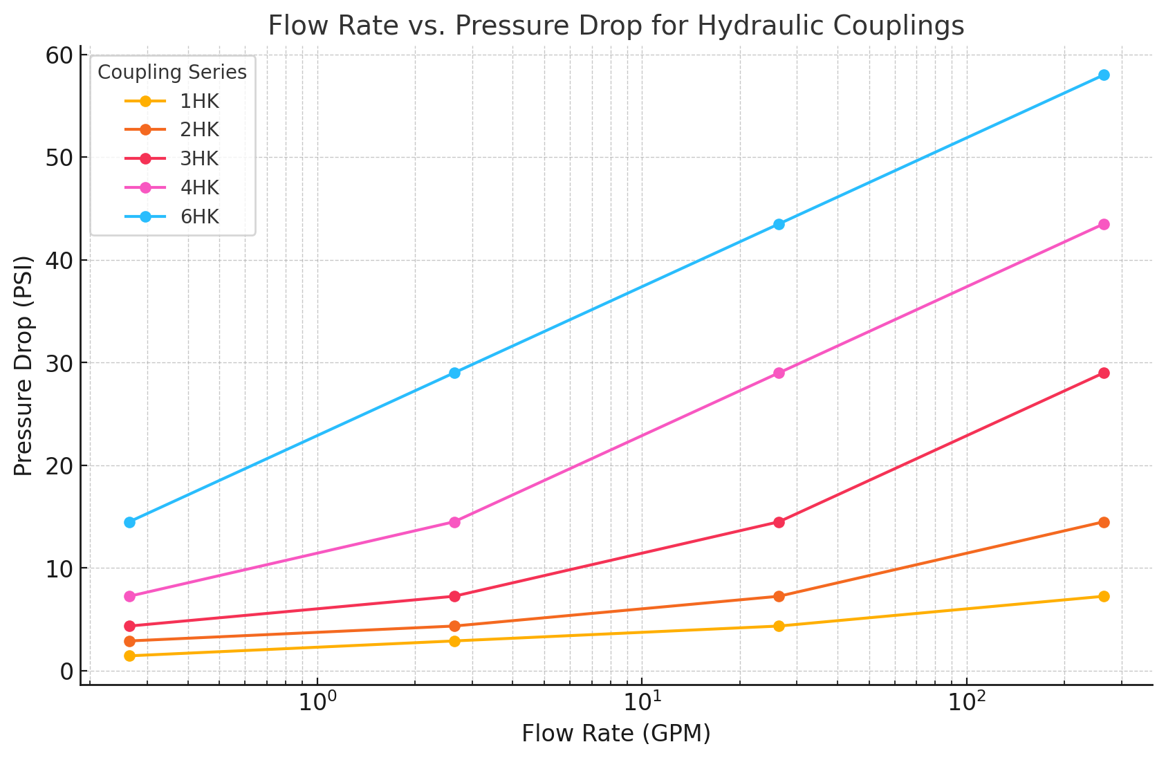
Flow Data
Seal Elastomer Data*
| Seal Elastomer** | Max. Operation Temperature Range |
|---|---|
| Nitrile (NBR) | -40°C to +121°C / -40°F to +250°F |
| Neoprene | -54°C to +100°C / -65°F to +212°F |
| EPDM | -54°C to +149°C / -65°F to +300°F |
| FKM | -29°C to +204°C / -15°F to +400°F |
* For reference only, based on Danfoss recommended temperatures.
** For seals not listed, contact Danfoss.
HK Series (Steel)
ISO 7241-1 B Interchange
Sockets/Female
| Part Number | Body Size (in) | Body Size (mm) | Thread Size (NPTF) | Thread Size (BSPP) | Thread Size (SAE) | A (in) | B (in) | Across Flats (in) | A (mm) | B (mm) | Across Flats (mm) |
|---|---|---|---|---|---|---|---|---|---|---|---|
| 1H11 | ⅛ | 5.0 | ⅛-27 | – | – | 1.91 | 0.98 | 0.56 | 48.5 | 24.9 | 14.2 |
| 1H4 | ⅛ | 5.0 | – | – | 7⁄16-20 | 2.06 | 0.98 | 0.69 | 52.3 | 24.9 | 17.5 |
| 2H16 | ¼ | 6.3 | ¼-18 | – | – | 2.26 | 1.14 | 0.75 | 57.4 | 29.0 | 19.1 |
| 2H16BS | ¼ | 6.3 | – | ¼-19 | – | 2.31 | 1.14 | 0.75 | 58.7 | 29.0 | 19.1 |
| 2H6 | ¼ | 6.3 | – | – | 9⁄16-18 | 2.40 | 1.14 | 0.88 | 61.0 | 29.0 | 22.4 |
| 3H21 | ⅜ | 10.0 | ⅜-18 | – | – | 2.56 | 1.42 | 0.88 | 65.0 | 36.1 | 22.4 |
| 3H21BS | ⅜ | 10.0 | – | ⅜-19 | – | 2.56 | 1.42 | 0.88 | 65.0 | 36.1 | 22.4 |
| 3H8 | ⅜ | 10.0 | – | – | ¾-16 | 2.74 | 1.42 | 1.00 | 69.6 | 36.1 | 25.4 |
| 4HP26 | ½ | 12.5 | ½-14 | – | – | 2.96 | 1.86 | 1.13 | 75.2 | 47.2 | 28.7 |
| 4HP26BS | ½ | 12.5 | – | ½-14 | – | 2.96 | 1.86 | 1.13 | 75.2 | 47.2 | 28.7 |
| 4HP10 | ½ | 12.5 | – | – | 7⁄8-14 | 3.05 | 1.86 | 1.25 | 77.5 | 47.2 | 31.8 |
| 6HP31 | ¾ | 20.0 | ¾-14 | – | – | 3.48 | 2.22 | 1.31 | 88.4 | 56.4 | 33.3 |
| 6HP31BS | ¾ | 20.0 | – | ¾-14 | – | 3.48 | 2.22 | 1.31 | 88.4 | 56.4 | 33.3 |
| 6HP12 | ¾ | 20.0 | – | – | 1-12 | 3.67 | 2.22 | 1.38 | 93.2 | 56.4 | 35.1 |
| 8HP36 | 1 | 25.0 | 1-11½ | – | – | 4.13 | 2.61 | 1.75 | 104.9 | 66.3 | 44.5 |
| 8HP36BS | 1 | 25.0 | – | 1-11 | – | 4.13 | 2.61 | 1.75 | 104.9 | 66.3 | 44.5 |
| 8HP16 | 1 | 25.0 | – | – | 1⁵⁄₁₂-12 | 4.13 | 2.61 | 1.88 | 104.9 | 66.3 | 47.8 |
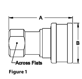
A=Overall Length, B=Maximum Diameter
To obtain connected length of coupling, add dimensions A (Fig. 1) and E (Fig. 3) together.
Sockets/Female
| Part Number | Body Size (in) | ISO Size (mm) | Thread Size (NPTF) | Thread Size (BSPP) | Fig. | A (in) | B (in) | Hex (in) | A (mm) | B (mm) | Hex (mm) |
|---|---|---|---|---|---|---|---|---|---|---|---|
| 10H41* | 1¼ | – | 1¼-11½ | – | 2 | 4.51 | 2.73 | 2.38 | 114.6 | 69.3 | 60.5 |
| 10H41BS* | 1¼ | – | 1¼-11½ | – | 2 | 4.51 | 2.73 | 2.38 | 114.6 | 69.3 | 60.5 |
| 12H41 | 1½ | 40 | 1¼-11½ | – | 2 | 4.82 | 3.23 | 2.38 | 122.4 | 82.0 | 60.5 |
| 12H41BS | 1½ | 40 | 1¼-11½ | – | 2 | 4.82 | 3.23 | 2.38 | 122.4 | 82.0 | 60.5 |
| 12H46 | 1½ | 40 | 1½-11½ | – | 2 | 4.82 | 3.23 | 2.38 | 122.4 | 82.0 | 60.5 |
| 12H46BS | 1½ | 40 | 1½-11½ | – | 2 | 4.82 | 3.23 | 2.38 | 122.4 | 82.0 | 60.5 |
| 20H51 | 2½ | 50 | 2-11½ | – | 2 | 5.55 | 4.11 | 3.75 | 141.0 | 104.4 | 95.3 |
| 20H51BS | 2½ | 50 | 2-11 | – | 2 | 5.55 | 4.11 | 3.75 | 141.0 | 104.4 | 95.3 |
| 20H56 | 2½ | 50 | 2½-8 | – | 2 | 6.14 | 4.11 | 3.75 | 156.0 | 104.4 | 95.3 |
| 20H56BS | 2½ | 50 | 2½-11 | – | 2 | 6.14 | 4.11 | 3.75 | 156.0 | 104.4 | 95.3 |
| 20H61 | 2½ | 50 | 3-8 | – | 2 | 7.00 | 4.11 | 4.00 | 177.8 | 104.4 | 101.6 |
| 20H61BS | 2½ | 50 | 3-11 | – | 2 | 7.00 | 4.11 | 4.00 | 177.8 | 104.4 | 101.6 |
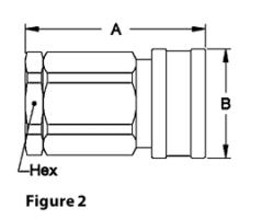
A=Overall Length, B=Maximum Diameter
* ISO 7241-1 Series B does not include 1-¼ inch body size couplings; therefore, Series 10HK is not covered by this standard
To obtain connected length of coupling, add dimensions A (Fig. 2) and E (Fig. 4) together
Plugs/Male
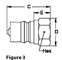
| Part Number | Body Size (in) | ISO Size (mm) | Thread Size (NPTF) | Thread Size (BSPP) | Thread Size (SAE) | Fig. | C (in) | D (in) | E (in) | Hex (in) | C (mm) | D (mm) | E (mm) | Hex (mm) |
|---|---|---|---|---|---|---|---|---|---|---|---|---|---|---|
| 1K11 | ⅛ | 5 | ⅛-27 | – | – | 3 | 1.26 | 0.65 | 0.44 | 0.56 | 32.0 | 16.5 | 11.2 | 14.2 |
| 1K4 | ⅛ | 5 | – | – | 7⁄16-20 | 3 | 1.41 | 0.79 | 0.59 | 0.69 | 35.8 | 20.1 | 15.0 | 17.5 |
| 2K16 | ¼ | 6.3 | ¼-18 | – | – | 3 | 1.52 | 0.87 | 0.56 | 0.75 | 38.6 | 22.1 | 14.2 | 19.1 |
| 2K16BS | ¼ | 6.3 | – | ¼-19 | – | 3 | 1.52 | 0.87 | 0.56 | 0.75 | 38.6 | 22.1 | 14.2 | 19.1 |
| 2K6 | ¼ | 6.3 | – | – | 9⁄16-18 | 3 | 1.66 | 1.01 | 0.61 | 0.88 | 42.2 | 25.7 | 15.5 | 22.4 |
| 3K21 | ⅜ | 10 | ⅜-18 | – | – | 3 | 1.76 | 1.01 | 0.61 | 0.88 | 44.7 | 25.7 | 15.5 | 22.4 |
| 3K21BS | ⅜ | 10 | – | ⅜-19 | – | 3 | 1.76 | 1.01 | 0.61 | 0.88 | 44.7 | 25.7 | 15.5 | 22.4 |
| 3K8 | ⅜ | 10 | – | – | ¾-16 | 3 | 1.94 | 1.14 | 0.79 | 1.00 | 49.3 | 33.0 | 19.3 | 25.4 |
C=Overall Length, D=Maximum Diameter, E=Exposed Length when Connected
To obtain connected length of coupling, add dimensions A (Fig. 1) and E (Fig. 3) together.
Plugs/Male
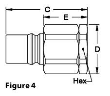
| Part Number | Body Size (in) | ISO Size (mm) | Thread Size (NPTF) | Thread Size (BSPP) | Fig. | C (in) | D (in) | E (in) | Hex (in) | C (mm) | D (mm) | E (mm) | Hex (mm) |
|---|---|---|---|---|---|---|---|---|---|---|---|---|---|
| 10K41* | 1¼ | – | 1¼-11½ | – | 4 | 4.25 | 2.74 | 2.33 | 2.38 | 108.0 | 69.6 | 59.2 | 60.5 |
| 10K41BS* | 1¼ | – | 1¼-11½ | 1¼-11 | 4 | 4.25 | 2.74 | 2.33 | 2.38 | 108.0 | 69.6 | 59.2 | 60.5 |
| 12K41 | 1½ | 40 | 1¼-11½ | – | 4 | 4.76 | 2.74 | 2.67 | 2.38 | 120.9 | 69.6 | 67.8 | 60.5 |
| 12K41BS | 1½ | 40 | 1¼-11 | 1¼-11 | 4 | 4.76 | 2.74 | 2.67 | 2.38 | 120.9 | 69.6 | 67.8 | 60.5 |
| 12K46 | 1½ | 40 | 1½-11 | – | 4 | 4.76 | 2.74 | 2.67 | 2.38 | 120.9 | 69.6 | 67.8 | 60.5 |
| 12K46BS | 1½ | 40 | 1½-11 | 1½-11 | 4 | 4.76 | 2.74 | 2.67 | 2.38 | 120.9 | 69.6 | 67.8 | 60.5 |
| 20K51 | 2½ | 60 | 2-11½ | – | 4 | 5.49 | 4.33 | 2.97 | 3.75 | 139.4 | 110.0 | 75.4 | 95.3 |
| 20K51BS | 2½ | 60 | 2-11 | – | 4 | 5.49 | 4.33 | 2.97 | 3.75 | 139.4 | 110.0 | 75.4 | 95.3 |
| 20K56 | 2½ | 60 | 2½-8 | – | 4 | 6.08 | 4.33 | 3.56 | 3.75 | 154.4 | 110.0 | 90.4 | 95.3 |
| 20K56BS | 2½ | 60 | 2½-11 | – | 4 | 6.08 | 4.33 | 3.56 | 3.75 | 154.4 | 110.0 | 90.4 | 95.3 |
| 20K61 | 2½ | 60 | 3-8 | – | 4 | 6.94 | 4.62 | 4.42 | 4.00 | 176.3 | 117.3 | 112.3 | 101.6 |
| 20K61BS | 2½ | 60 | 3-11 | – | 4 | 6.94 | 4.62 | 4.42 | 4.00 | 176.3 | 117.3 | 112.3 | 101.6 |
C=Overall Length, D=Maximum Diameter, E=Exposed Length when Connected
* ISO 7241-1 Series B does not include 1-¼ inch body size couplings; therefore, Series 10HK is not covered by this standard
To obtain connected length of coupling, add dimensions A (Fig. 2) and E (Fig. 4) together
Dust Plugs and Dust Caps Accessories
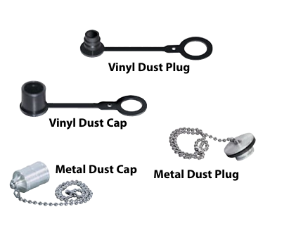
| Coupling Series | Plug Dust Cap Part No. (Metal) | Plug Dust Cap Part No. (Vinyl) | Socket Dust Plug Part No. (Metal) | Socket Dust Plug Part No. (Vinyl) |
|---|---|---|---|---|
| 1HK | XPDC1HK* | XPPDC1HK | SDC1HK* | XPSDC1HK |
| 2HK | XPDC2HK* | XPPDC2HK | SDC2HK* | XPSDC2HK |
| 3HK | XPDC3HK* | XPPDC3HK | SDC3HK* | XPSDC3HK |
| 4HK | XPDC4HK** | XPPDC4HK(RD)*** | SDC4HK** | XPSDC4HK(RD)*** |
| 6HK | XPDC6HK** | XPPDC6HK(RD)*** | SDC6HK** | XPSDC6HK(RD)*** |
| 8HK | XPDC8HK** | XPPDC8HK(RD)*** | SDC8HK** | XPSDC8HK(RD)*** |
| 12HK | XPDC12HK** | – | SDC12HK** | – |
| 20HK | XPDC20HK** | – | SDC20HK** | – |
*Brass **Aluminum *** Offered in red by adding RD to end of part number
